Illustrated research note · Manuscript under review
Bistable shape-morphing kirigami
Designing a cut sheet that opens into a curved surface and holds its shape.
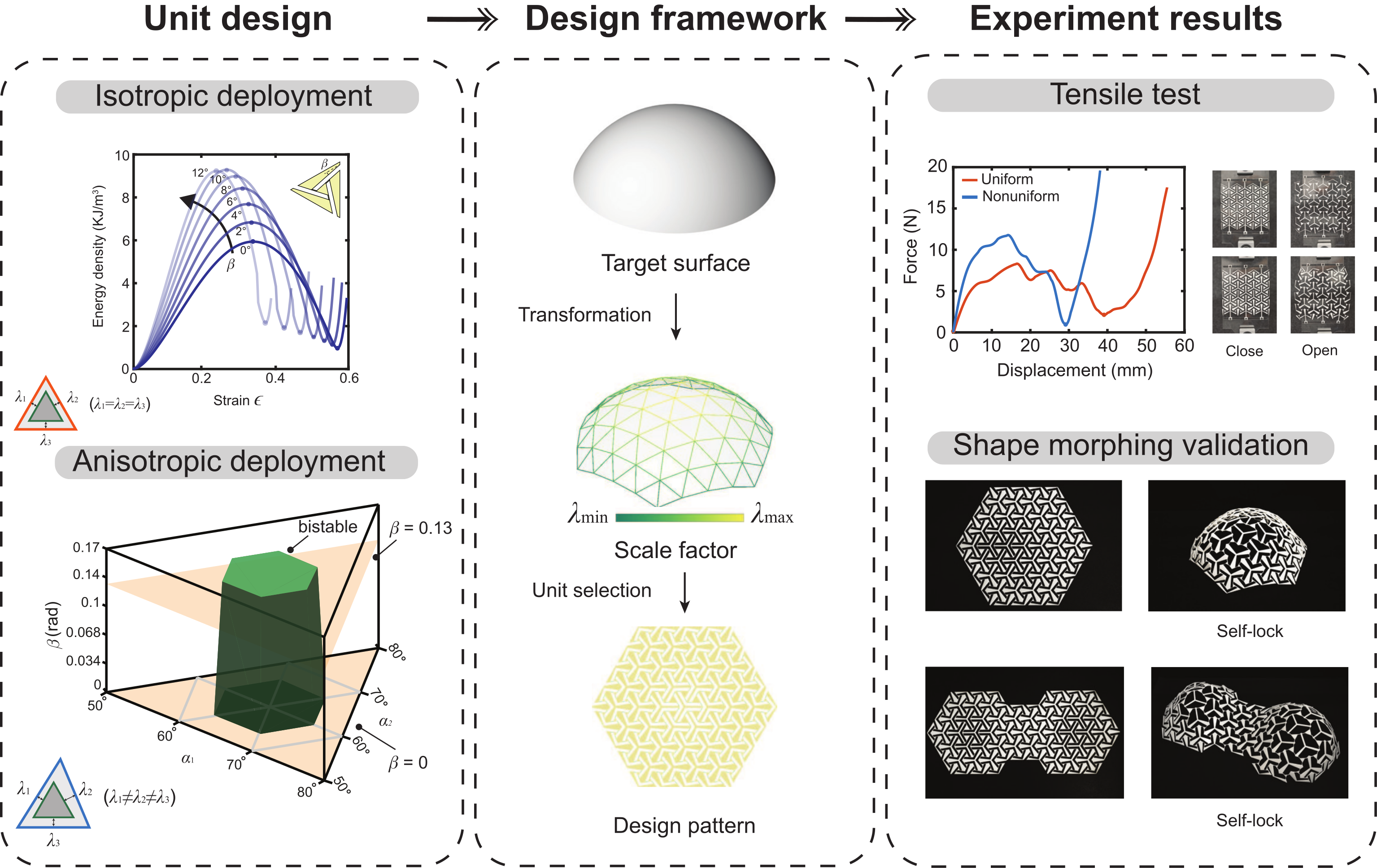
Thin elastic ligaments can give a triangular unit two stable configurations. We match their mechanical response to the different stretches required across a curved surface, encoding both the target shape and its stability in a flat cut pattern. [1]
01 A ligament-based bistable unit
Three slender ligaments connect a triangular core to its surrounding flanks. As the unit opens, these ligaments bend and stretch. Their geometry can create an energy barrier between a closed state and a second, deployed equilibrium: the unit can stay open after the load is removed. [1, Fig. 1]
- Where does it settle?
- The strain at the deployed energy minimum, εbist, sets the unit’s stable expansion.
- How deep is the well?
- η = (Emax − Emin) / Emax measures its relative depth: Emin is the deployed local minimum and Emax is the intervening barrier.
The ligament angle β tunes the deployed strain and energy landscape. Ligament thickness t strongly affects the energy barrier. This builds on earlier work on geometric bistable motifs and slender ligaments in rigid solids. [2] [3]
How the ligament model works
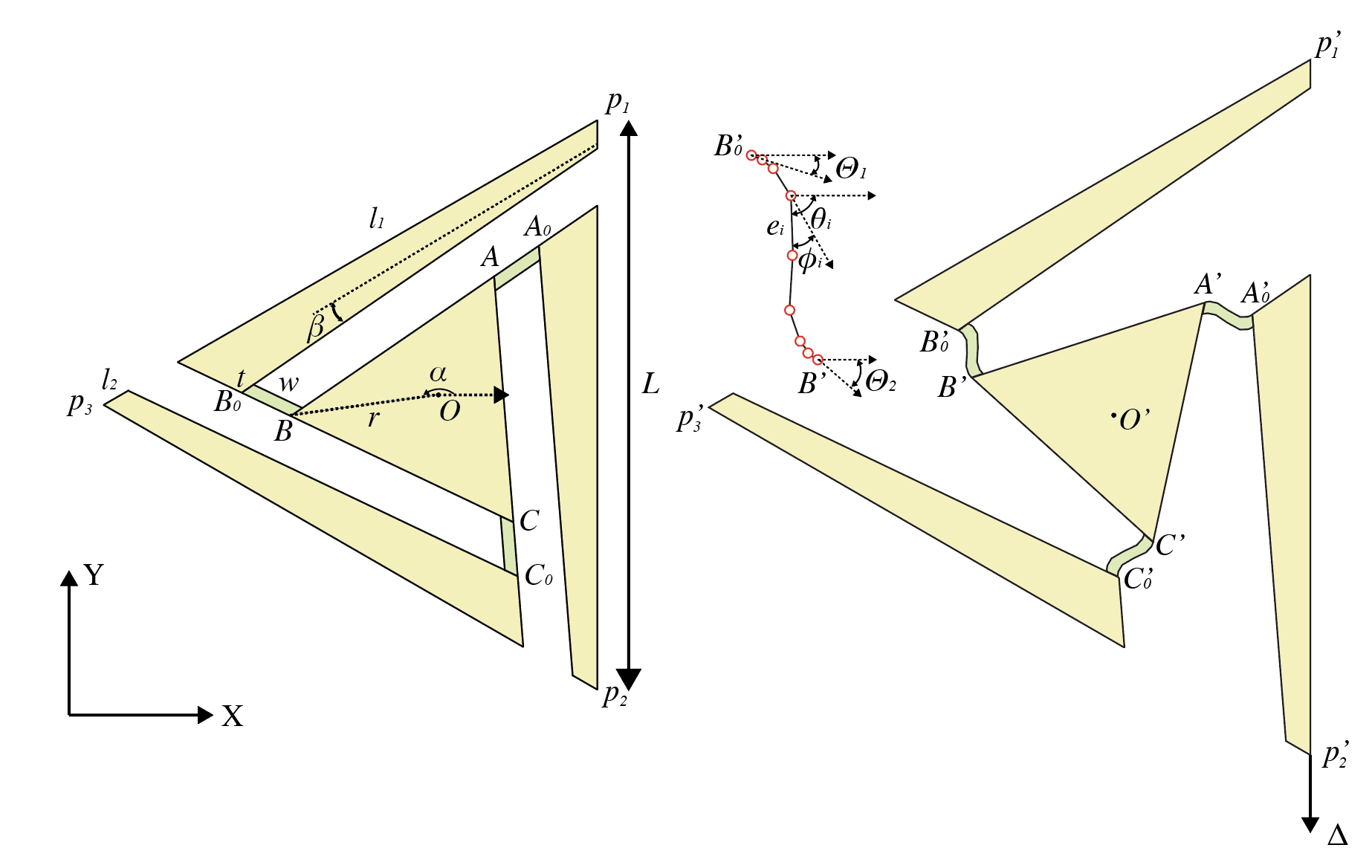
The model treats the core and flanks as rigid and concentrates compliance in the ligaments. A Hencky bar-chain represents each ligament with extensible bars and rotational springs. Its energy combines bending and stretching:
Elig = ½ ∑i kb,i φi² + ½ ∑i ks,i ei²
The energy is minimised subject to end-position and tangent constraints. The bars and springs are a numerical representation of a continuous ligament, rather than physical pin joints. See the paper’s Eq. (2) and Supplementary Note S1. [1]
02 Smooth geometry, finite triangles
A smooth conformal map preserves local angles. At any one point, the infinitesimal stretch is the same in every direction, but its magnitude can vary from point to point. A finite triangular cell samples that variation across three different edges. [1, Supplementary Note S4]
Smooth setting
Discrete setting
For deployment, define each edge stretch as λi = ℓi,deployed / ℓi,flat, for i = 1, 2, 3. These three values need not be equal.
Local conformality does not make every finite triangle isotropic.
03 Why the three edge stretches matter
Equal overall expansion does not guarantee the same stability. In the comparison below, the same unit geometry reaches approximately the same area expansion (about 2.4), yet changing the balance between its three edge stretches removes the second energy minimum. [1, Fig. 4]
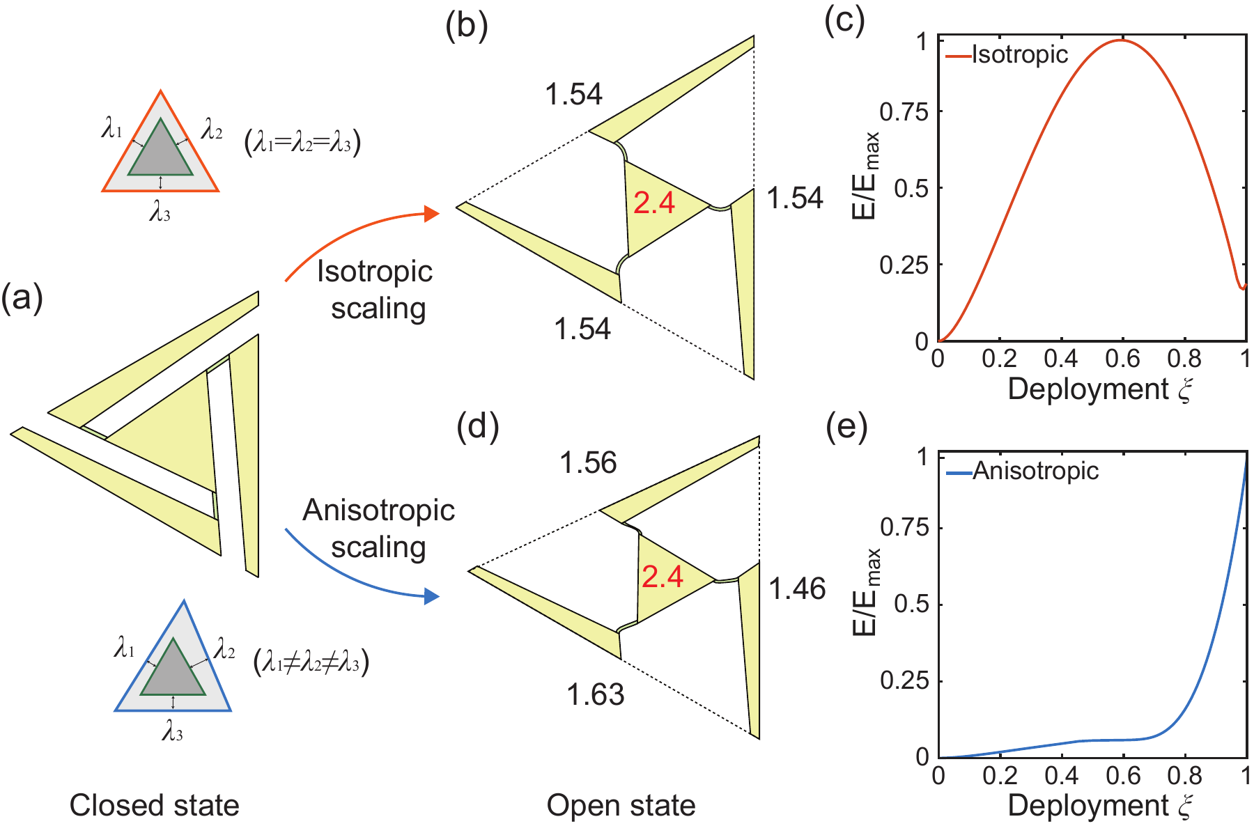
This does not mean anisotropy always destroys bistability. It means stability must be checked for the actual combination of edge stretches. The framework maps admissible bistable regions and selects a unit geometry for each cell’s particular deformation. [1, Fig. 5]
04 An anisotropy-aware design workflow
Boundary First Flattening supplies a planar conformal map of the target surface. [4] Conformal surface design provides the geometric starting point; here, unit-level mechanics adds the requirement that the deployed configuration should also be stable. [5]
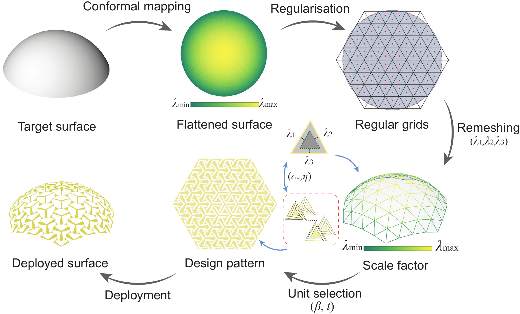
- Map. Flatten the target surface and obtain its spatially varying conformal scale.
- Resolve. Place a regular triangular grid on the flattened domain. Interpolate the scale field barycentrically onto the grid nodes, then convert the nodal values into three edge stretches for each cell.
- Match. Select ligament geometry from a precomputed library: match the stable expansion to the target deformation and favour a deeper relative energy well, η. Thickness provides a further means of tuning the barrier.
- Assemble. Combine the selected units into a flat, connected cut pattern. For the demonstrated designs, the scale field is globally rescaled so the boundary rim units remain undeployed.
05 From a flat sheet to a stable surface
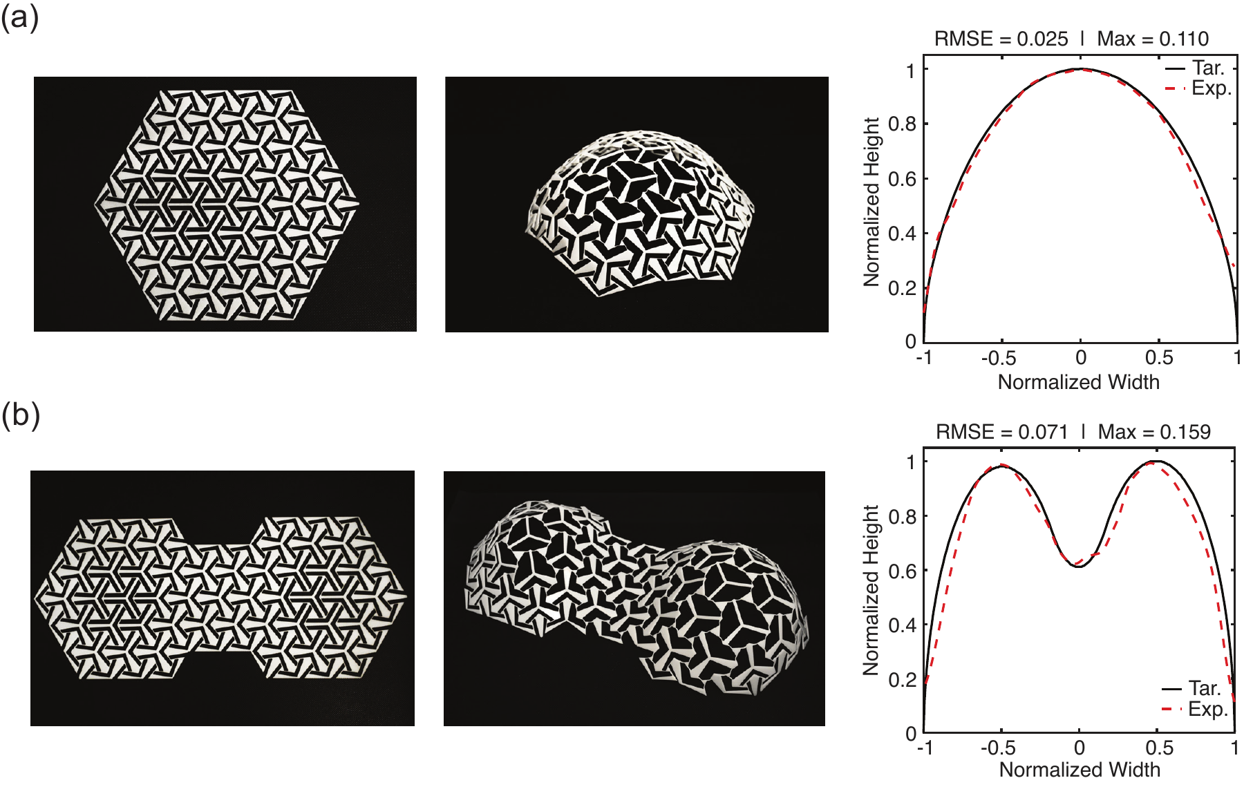
The dome and double-dome examples connect the local unit design to a complete sheet. The animations show the prescribed deployment path alongside the summed in-plane energy of its units. [1, Fig. 7]
Experiments with 1.5 mm Delrin sheets demonstrate freestanding deployed dome and double-dome structures. Their front-view contours are compared with the target shapes below. The reported contour errors measure these projected profiles, rather than the full three-dimensional surface. [1, Fig. 8]
Scope. The available unit geometries have a bounded stretch range. The design energy accounts for in-plane ligament mechanics, and additional out-of-plane bending can affect stability. Negative-curvature regions can suppress bistability, so the method does not guarantee a stable realisation of every target surface. [1]
References & figure credits
- Ying, X. & Dias, M. A. Instability-induced bistable shape-morphing kirigami structures. arXiv:2607.26941 (2026). Manuscript under review. Technical references in this note refer to version 1 and its supplementary information.
- Rafsanjani, A. & Pasini, D. Bistable auxetic mechanical metamaterials inspired by ancient geometric motifs. Extreme Mechanics Letters 9, 291–296 (2016).
- Shang, X., Liu, L., Rafsanjani, A. & Pasini, D. Durable bistable auxetics made of rigid solids. Journal of Materials Research 33, 300–308 (2018).
- Sawhney, R. & Crane, K. Boundary First Flattening. ACM Transactions on Graphics 37(1), Article 5. Published online in 2017.
- Wang, Y., Ren, Y. & Chen, T. From Kirigami to Hydrogels: A Tutorial on Designing Conformally Transformable Surfaces. Journal of Applied Mechanics 90(4), 044801 (2023).
Figures are the authors’ original graphical abstract and research figures. Animations and the unit diagram come from Xiaoyuan Ying’s SES presentation (slides 4, 5, 11 and 16), converted for web playback without changing the scientific geometry or plotted data. All animations start paused.